
How to Choose Shock Absorbing Casters
Shock absorbing casters offer several benefits, including cargo protection, noise reduction, and the ability to roll over some obstructions, just to name a few. However, choosing the wrong shock absorbing caster may actually do more harm than good. Shock Absorbing casters utilize a spring to dissipate shock, choosing the wrong spring can negate all benefits and actually diminish performance below levels of conventional casters.
All to often, the focus is simply on maximum weight capacity, in actuality, the following are key factors to help choose shock absorbing casters:
Initial Force– Each and every spring, no matter how small or how large, has a measurable force that must be applied to the spring to initiate deflection of the spring configuration.
Linear Deflection– Once the spring begins to deflect it is designed to provide a very predictable deformity of the spring configuration in relation to the amount of force that is applied. This is a linear relationship (projected in the straight line in the associated graph) and is directly proportional, in that X amount of force will result in Y amount of deformity, at every point along the line.
Full Deflection– At the end point the spring is completely deformed as a response to the force and no further pressure will change the spring unless the pressure is so great that in fact deforms the material that the spring is made of.
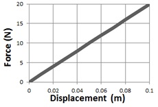
Spring displacement is linear until point of full deflection
When designing and building spring loaded casters each one of these characteristics must be considered to have a spring loaded caster that properly functions. Springs are made with a variety of different characteristics that impact each of the three areas discussed:
Pre-load of the Spring (Initial Force)– In the engineering and manufacturing of the caster there must be a pre-load applied to the spring. In the graph supplied the preload is approx 250 lbs of force. At this point any additional force that is applied to the caster will result in spring deflection and noise reduction. Any load applied to the caster below this pre-load will result in zero deflection.
Operational Force (Linear Deflection)– In this area of the graph the spring should function in a similar fashion to the theoretical deflection curve. As you can see in the graph each of the tested cases performed in a very predictable fashion for the entire length of this segment of the graph. This means that for each pound of force applied there is a very predictable movement of the spring. The graph also depicts an operation sweet spot that with proper planning and complete understand of the operation the spring would ”live in this area” of the graph. If the engineering of spring location and spring alignment is not properly applied to the design the end result will not be a linear graph and the operation will not be optimal and most likely will lead to damage to the caster, cart or payload.
Bottom Out (Full Deflection)– At this point the caster is no longer a spring loaded caster and the caster will function as regular caster without any sound-deadening effect. Even in properly engineered casters this can happen with shock loading of the cart, over loading of the cart or hitting an obstruction or pot hole during operation. If the process of ”bottoming out” occurs frequently during the normal operation, most likely the caster is not properly designed for the application.